Previous Chapter LLUs Home Next Chapter IndexNCAR Graphics depends on three different coordinate systems and a transformation between them to plot your data to the screen. Before any plotting can be done, this transformation must be defined, so it is a critical part of your graphics program. Each of the coordinate systems and the transformation are defined below.


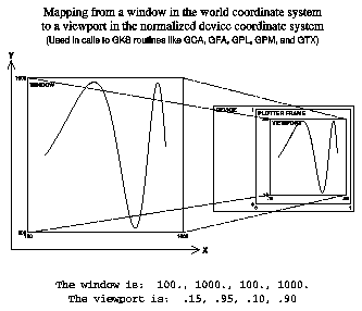
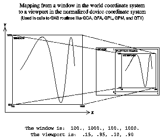
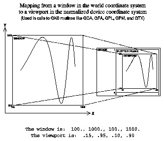
The World Coordinate System (WCS) is the system in which you perform your calculations. It can have units of feet, meters, millibars, or whatever engineering units apply to the calculations. World coordinates are Cartesian coordinates expressed as real numbers. You can select a rectangular subspace of world coordinates for output; this space is called a "window." In world coordinates, both axes must monotonically increase starting with a data origin in the lower left coordinate of the frame.
Normalized Device Coordinates (NDCs) is a device-independent coordinate system used by GKS as an addressing system for a virtual (any) plotting device. In GKS, you must perform a transformation from WCs to NDCs. Whereas WCs have variable ranges, NDCs have a constrained range limited to (0.,0.) in the lower left corner and (1.,1.) in the upper right corner. A rectangular subspace of NDCs can be selected for output; this space is called a "viewport."
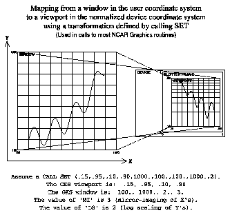
The user coordinate system in NCAR Graphics adds two important extensions to GKS world coordinates: "mirror-imaging" of an axis, and "nonlinear scaling" of an axis. Thus, in user coordinates, windows can be defined in which the horizontal coordinate of the window might be meters varying from 1000. at the left to 100. at the right (mirror-imaging), and the vertical coordinate might vary from 102 at the bottom to 103 at the top in logarithmic scaling.
If you are working in Cartesian space with linear scaling and standard minimum to maximum axis scaling, then world coordinates and user coordinates are equivalent.
The process of transforming data from WCs into NDCs for output on the plotting device is called a normalization transformation. The NCAR Graphics GKS-0A package currently supports two normalization transformation types. Type 0 defines an identity transformation in which the WCs, like NDCs, have horizontal and vertical axes ranging from 0. to 1. This is the transformation used to facilitate putting an object such as a title at a specific location on the frame. A type 1 normalization transformation allows the WCs to have whatever range of values is desired.
See "Appendix A: The use of X/Y coordinates in NCAR Graphics" for a complete description of NCAR Graphics coordinate systems.
The graphic shows a normalization transformation from world coordinates to NDCs, in which there is mirror-imaging and nonlinear scaling of axes.

1 CALL SET(VPL,VPR,VPB,VPT,1000.,100.,100.,1000.,2)
CALL SET (VPL, VPR, VPB, VPT, WDL, WDR, WDB, WDT, LS)
Every call to SET redefines GKS normalization transformation 1 with the new viewport and window coordinates, axis scaling, and axis mirror-imaging. This normalization transformation 1 will be in effect until it is changed by either another SET call or by a call to the GKS routine GSELNT.
Caution: If you use GSELNT to define a new normalization transformation, you will still have the mirror-imaging and linear/log scaling established by the last SET call. If the last SET call used nonlinear axis scaling or mirror-imaging of an axis, you may need to do another SET call to alter these settings.

1     CALL GETSET(VPLS,VPRS,VPBS,VPTS,WDLS,WDRS,WDBS,WDTS,LSS)
2     CALL SET(VPL,VPR,VPB,VPT,1000.,100.,100.,1000.,2)
3     CALL SET(VPLS,VPRS,VPBS,VPTS,WDLS,WDRS,WDBS,WDTS,LSS)
CALL GETSET (VPL, VPR, VPB, VPT, WDL, WDR, WDB, WDT, LS)
See "Appendix A: The use of X/Ycoordinates in NCAR Graphics" for a complete description of NCAR Graphics coordinate systems.
Previous Chapter LLUs Home Next Chapter Index