In addition to its own
user coordinate space, NCAR Graphics
uses two GKS coordinate systems: world coordinates (WC) and normalized
device coordinates (NDC). Both are defined in terms of floating point
numbers.
A world coordinate system is a Cartesian coordinate system that
is linear along both axes.
A world coordinate system can have units of
feet, meters, millibars, or whatever
engineering units apply to the calculations. World coordinates are
expressed as real numbers. You can select a rectangular subspace
of world coordinates for output.
This is a device-independent coordinate system used by GKS as an
addressing system for a virtual plotting device; it is a two dimensional
Cartesian space that has horizontal and vertical ranges of 0. to 1.
inclusive. In GKS, a transformation is performed from a subrectangle
of world coordinates (called a
"window"
) to
a subrectangle of the normalized device coordinates (NDC). The rectangular
subspace of NDC is called a
"viewport.".
To ensure that squares in
world coordinates are mapped onto squares on the output plotting device,
the maximum display surface on that device will be the largest square
which will fit on the plotting device. The NCAR Graphics
CGM interpreter,
ctrans, centers the maximum viewport on an output plotting device.
X11
output is centered in the output window. PostScript output is centered
on the page by default, but options exist for
positioning PostScript output
anywhere on the page.
In NCAR Graphics, Normalized Device Coordinates are sometimes referred to as
"Fractional Coordinates".
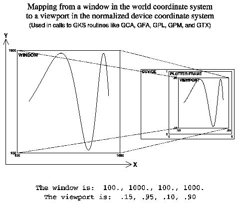
The linear transformation between the world coordinate window and the
NDC viewport is called a normalization transformation. For example, the
horizontal coordinates of the window might be from 100. to 1000. meters.
The horizontal coordinates of the viewport might be.15 to.95. Diagram 1
shows a typical GKS normalization transformation.
Diagram 1
- A typical GKS normalization transformation

A user coordinate system is any coordinate system in which
user calculations are performed. This may be polar coordinates, log
scaled coordinates, or any other such coordinate system.
If you are working in a user coordinate space that is a Cartesian
space with no log scaling or mirror
imaging of an axis, then world coordinates and user coordinates are
equivalent.
GKS requires
that both windows and viewports have linear scaling. GKS also requires
that the horizontal coordinate increase from left to right, and that
the vertical coordinate increase from bottom to top. Thus, the viewport
coordinate (0.,0.) references the lower left corner of a plotting surface.
NCAR Graphics provides extensions to GKS world coordinates to allow for
mirror imaging
of an axis, and
log scaling
of an axis. If you are using
any other coordinate system, then you will have to map it into one of
the coordinate systems supported by NCAR Graphics before making GKS calls.
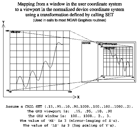
In order to use the log scaling or mirror-imaging features of the NCAR
Graphics user coordinate spaces, you must establish your coordinate mapping
transformations. The easiest way to do this to by using a
SET call.
In user coordinates, windows can be defined in which
the horizontal coordinate of the window might be meters ranging from 1000.
at the left to 100. at the right (mirror imaging), and the vertical
coordinate might vary from 10**2 at the bottom to 10**3 at the top in
logarithmic scaling.
For a detailed description of the relationship between the GKS coordinate
systems and User Coordinates, see
NCAR Graphics Fundamentals, UNIX Version, Appendix A.
Diagram 2
- A normalization transformation with mirror imaging and log scaling
 In certain places in the documentation for LLUs, reference is made to
Plotter Address Units
(PAUs). PAUs are integers defined in the range
1 to 1024 and map linearly to normalized device coordinate space. For
example, if you wanted a length of .01 in normalized device coordinate
space, but were required to specify this as a PAU, then you would use
the integer value 102 (.01*1024).
Links:
GKS Index,
GKS Home

